Axis mechanical engineering. Shafts and axes in industry: applications and types
Classification of shafts and axles of construction machines. What types of shafts are used in machines? The difference between the processing of shafts and axles, mechanisms in the form of paired shafts.
Types of machine shafts and axles
Types of shafts
Axles- support rotating machine parts. They can be rotating or stationary.
Shafts- not only support, but also transmit rotation.
There are: straight, crank and cranked.
Shafts are designed for the simultaneous action of torque and bending moments.
The axles are designed only for bending.
- shaft with straight axis;
- crankshaft;
- flexible shaft;
- cardan shaft
Types of axes
- motionless;
- movable.
Axles and shafts differ from other machine parts in that they carry gears, pulleys, and other rotating parts. According to operating conditions, axles and shafts differ from each other.
An axis is a part that only supports the parts mounted on it. The axis does not experience torsion, since the load on it comes from the parts located on it. It works on bending and does not transmit torque.
As for the shaft, it not only supports the parts, but also transmits torque. Therefore, the shaft experiences both bending and torsion, and sometimes also compression and tension. Among the shafts, there are torsion shafts (or simply torsion bars), which do not support the rotation of parts and work exclusively on torsion. Examples are a car's driveshaft, a rolling mill's coupling roller, and much more.
The section in the shaft or axle support is called a journal if it receives a radial load, or a fifth if an axial load is applied to it. The end journal that receives the radial load is called the tenon, and the journal located at some distance from the end of the shaft is called the journal. Well, that part of the shaft or axis that limits the axial movement of parts is called a shoulder.
The seating surface of the axle or shaft, on which the rotating parts are actually mounted, is often made cylindrical and less often conical to facilitate the installation and removal of heavy parts when high centering accuracy is required. The surface that provides a smooth transition between steps is called fillet. The transition can be made using a groove that allows the grinding wheel to exit. Stress concentration can be reduced by reducing the depth of the grooves and increasing the rounding of the grooves and dumbbells as much as possible.
To make the installation of rotating parts on an axle or shaft easier, as well as to prevent hand injuries, the ends are chamfered, that is, slightly ground to a cone.
Types of axles and shafts
The axle can be rotating (for example, the axle of a carriage) or non-rotating (for example, the axle of a block of a machine for lifting goods).
Well, the shaft can be straight, cranked or flexible. Straight shafts are the most common. Crankshafts are used in crank transmissions of pumps and engines. They convert reciprocating movements into rotational ones, or vice versa. As for flexible shafts, they are, in fact, multi-retractable torsion springs twisted from wires. They are used to transmit torque between machine components if they change position relative to each other during operation. Both crankshafts and flexible shafts are classified as special parts and are taught in special training courses.
Most often, the axis or shaft has a circular solid cross-section, but they can also have an annular cross-section, which makes it possible to reduce the total weight of the structure. The cross-section of some sections of the shaft may have a keyway or splines, or may be profiled.
With a profile connection, the parts are fastened together using contact along a round, non-smooth surface and, in addition to torque, can also transmit an axial load. Despite the reliability of the profile connection, it cannot be called technologically advanced, so their use is limited. The spline connection is classified according to the shape of the teeth profile - it can be straight-sided, involute or triangular.
Shafts and axles
PLAN LECTIONS
General information.
Materials and processing of shafts and axles.
Criteria for performance and calculation of shafts and axes.
Calculations of shafts and axes.
General information
Shafts- these are parts that serve to transmit torque along their axis and hold other parts located on them (wheels, pulleys, sprockets and other rotating machine parts) and perceive the acting forces.
Axles- these are parts that only hold the parts installed on them and perceive the forces acting on these parts (the axle does not transmit useful torque).
Classification of shafts and axles
Valov's classification groups the latter according to a number of characteristics: by purpose, by cross-sectional shape, by the shape of the geometric axis, by the external outline of the cross-section, by relative rotation speed and by location at the node .
By purpose they are distinguished:
gear shafts, on which wheels, pulleys, sprockets, couplings, bearings and other gear parts are installed. In Fig. eleven, A The transmission shaft is shown in Fig. eleven, b– transmission shaft;
main shafts(Fig. 11.2 - machine spindle), on which not only gear parts are installed, but also the working parts of the machine (connecting rods, turbine disks, etc.).
The following are made according to the cross-sectional shape:
solid shafts;
hollow shafts provide weight reduction or placement inside another part. In large-scale production, hollow welded shafts made from wound tape are used.
According to the shape of the geometric axis they produce:
straight shafts:
A) constant diameter(Fig. 11.3). Such shafts are less labor-intensive to manufacture and create less stress concentration;
b) stepped(Fig. 11.4). Based on the strength condition, it is advisable to design shafts of variable cross-section, approaching in shape to bodies of equal resistance. The stepped shape is convenient for manufacturing and assembly; the ledges can absorb large axial forces;
V) with flanges. Long shafts are composite, connected by flanges;
G) with cut gears(gear shaft);
crankshafts(Fig. 11.5) in crank gears they serve to convert rotational motion into reciprocating motion or vice versa;
flexible shafts(Fig. 11.6), which are multi-lead torsion springs twisted from wires, are used to transmit torque between machine components that change their relative position in operation (portable tools, tachometer, dental drills, etc.).
According to the external outline of the cross section, the shafts are:
smooth;
keyed;
splined;
profile;
eccentric.
According to the relative speed of rotation and location in the unit (gearbox), shafts are produced:
high-speed And input (leading)(pos. 1 rice. 11.7);
medium speed And intermediate(pos. 2 rice. 11.7);
slow-moving And weekend (slave)(pos. 3 rice. 11.7).


Rice. 11.2 Fig. 11.3


| |
|||||
| |
|||||
| |
|||||


Rice. 11.7 Fig. 11.8
Classification. The axes can be stationary (Fig. 11.8) or rotating together with the parts mounted on them. Rotating axles provide better operating conditions for bearings; stationary axles are cheaper, but require bearings to be built into parts rotating on the axes.
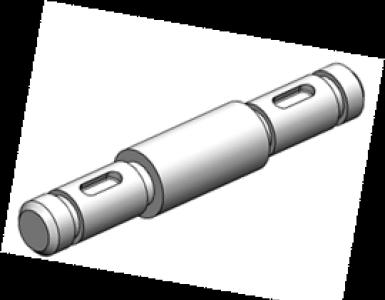
Designs of shafts and axles. The most common is the stepped shaft shape. Parts are most often secured to shafts with prismatic keys (GOST 23360–78, GOST 10748–79), straight-sided splines (GOST 1139–80) or involute splines (GOST 6033–80) or fits with guaranteed interference. The supporting parts of the shafts and axles are called axles. The intermediate axles are called necks, the end axles are called tenons. The supporting areas that take the axial load are called heels. Thrust bearings serve as supports for the heels.
In Fig. 11.9 shows the structural elements of the shafts, where 1 – prismatic key, 2 – splines, 3 – axle, 4 – heel, 5 – cylindrical surface, 6 – conical surface, 7 – ledge, 8 - shoulder, 9 – groove for the stop ring, 10 – threaded section, 11 – fillet, 12 – groove, 13 – chamfer, 14 – center hole.
The journals of shafts and axles operating in rolling bearings are almost always cylindrical, and in plain bearings they are cylindrical, conical or spherical (Fig. 11.10.)
The main application is cylindrical journals (Fig. 11.10, A, b) as simpler ones. Conical journals with small taper (Fig. 11.10, V) are used to regulate the clearance in bearings and sometimes for axial fixation of the shaft. Spherical journals (Fig. 11.10, G) due to the difficulty of their manufacture, they are used when it is necessary to compensate for significant angular displacements of the shaft axis.


a B C D
Landing surfaces under the hubs of various parts (according to GOST 6536–69 from the normal series), mounted on the shaft, and the end sections of the shafts are made cylindrical (pos. 5 rice. 11.9, GOST 12080–72) or conical (pos. 6 rice. 1.9, GOST 12081–72). Conical surfaces are used to ensure quick release and a given tension, increasing the accuracy of centering of parts.
For axial fixation of parts and the shaft itself, use ledges(pos. 7 rice. 11.9) and shoulders shaft (pos. 8 rice. 11.9, GOST 20226–74), conical sections of the shaft, retaining rings(pos. 9 rice. 11.9, GOST 13940–86, GOST 13942–86) and threaded sections (pos. 10 rice. 11.9) under nuts(GOST 11871–80).
Transitional areas from one section of the shaft to another and the ends of the shafts are made with grooves(pos. 12 rice. 11.9, fig. 11.11, GOST 8820–69), chamfered(pos. 13 rice. 11.9, GOST 10948–65) and fillets. Radius R fillets of constant radius (Fig. 11.11, A) choose less than the radius of curvature or the radial size of the chamfer of the mounted parts. It is desirable that the radius of curvature in highly stressed shafts be greater than or equal to 0.1 d. It is recommended to take fillet radii as large as possible to reduce load concentration. When the radius of the fillet is severely limited by the radius of the rounding of the edges of the mounted parts, spacer rings are installed. Fillets of a special elliptical shape and with an undercut or, more often, fillets outlined by two radii of curvature (Fig. 11.11, b), used when transitioning fillets to a step of smaller diameter (makes it possible to increase the radius in the transition zone).
Application of grooves (Fig. 11.11, V) can be recommended for non-critical parts, since they cause significant stress concentrations and reduce the strength of shafts under variable stresses. Grooves are used for the exit of grinding wheels (significantly increasing their durability during processing), as well as at the ends of threaded sections for the exit of thread-cutting tools. The grooves must have the maximum possible radii of curvature.

a B C
The ends of the shafts, in order to avoid crushing and damage to the hands of workers, are made with chamfers to facilitate fitting of parts.
Mechanical processing of shafts is carried out in centers, therefore, center holes should be provided at the ends of the shafts (pos. 14 rice. 11.9, GOST 14034–74).
The length of the axles usually does not exceed 3 m; the length of solid shafts, according to the conditions of manufacture, transportation and installation, should not exceed 6 m.
Axes serve to support various machine parts and mechanisms rotating with them or on them. The rotation of the axis, together with the parts installed on it, is carried out relative to its supports, called bearings. An example of a non-rotating axis is the axis of a lifting machine block (Fig. 1, a), and a rotating axis is a carriage axle (Fig. 1, b). The axles take the load from the parts located on them and bend.
Rice. 1Designs of axles and shafts.
Shafts, unlike axles, are designed to transmit torque and, in most cases, to support various machine parts rotating with them relative to the bearings. The shafts that carry the parts through which torque is transmitted receive loads from these parts and, therefore, work simultaneously in bending and torsion. When axial loads are applied to parts mounted on shafts (bevel gears, worm wheels, etc.), the shafts additionally work in tension or compression. Some shafts do not support rotating parts (drive shafts of cars, connecting rolls of rolling mills, etc.), so these shafts work only in torsion. Based on their intended purpose, they distinguish between gear shafts, on which gears, sprockets, couplings and other gear parts are installed, and main shafts, on which not only gear parts are installed, but also other parts, such as flywheels, cranks, etc.
The axes represent straight rods(Figure 1, a, b), and the shafts are distinguished straight(Fig. 1, c, d), cranked(Fig. 1, e) and flexible(Fig. 1, f). Straight shafts are widespread. Crankshafts in crank transmissions serve to convert reciprocating motion into rotational motion or vice versa and are used in piston machines (engines, pumps). Flexible shafts, which are multi-lead torsion springs twisted from wires, are used to transmit torque between machine components that change their relative position during operation (mechanized tools, remote control and monitoring devices, dental drills, etc.). Crankshafts and flexible shafts are special parts and are studied in the appropriate special courses. Axes and shafts in most cases are of a solid round, and sometimes of an annular cross-section. Individual sections of the shafts have a round solid or annular section with a keyway (Fig. 1, c, d) or with splines, and sometimes a profile section. The cost of axles and shafts of annular section is usually higher than that of a solid section; they are used in cases where it is necessary to reduce the mass of the structure, for example in aircraft (see also the axes of the satellites of the planetary gearbox in Fig. 4), or to place another part inside. Hollow welded axles and shafts, made from a tape located along a helical line, reduce weight by up to 60%.
Axles of short length are made of the same diameter along the entire length (Fig. 1, a), and long and heavily loaded axles are made shaped (Fig. 1, b). Depending on the purpose, straight shafts are made either of constant diameter along the entire length (transmission shafts, Fig. 1, c), or stepped (Fig. 1, d), i.e. of different diameters in certain areas. The most common are stepped shafts, since their shape is convenient for installing parts on them, each of which must pass freely to its place (for gearbox shafts, see the article “Gear reducers” Fig. 2; 3; and “Worm gear” Fig. 2 ; 3). Sometimes shafts are made integral with gears (see Fig. 2) or worms (see Fig. 2; 3).
 Rice. 2
The sections of axles and shafts with which they rest on bearings are called axles when perceiving radial loads, and heels when perceiving axial loads. End journals operating in plain bearings are called spikes(Fig. 2, a), and the axles located at some distance from the ends of the axles and shafts - necks(Fig. 2, b). The journals of axles and shafts operating in plain bearings are cylindrical (Fig. 2, a), conical(Fig. 2, c) and spherical(Fig. 2, d). The most common are cylindrical panels, as they are the simplest, most convenient and cheapest to manufacture, install and operate. Conical and spherical journals are used relatively rarely, for example, to adjust the clearance in bearings of precision machines by moving the shaft or bearing shell, and sometimes for axial fixation of the axis or shaft. Spherical journals are used when the shaft, in addition to rotational movement, must undergo angular movement in the axial plane. Cylindrical journals operating in plain bearings are usually made of a slightly smaller diameter compared to the adjacent section of the axle or shaft, so that, thanks to the shoulders and shoulders (Fig. 2, b), the axles and shafts can be secured against axial displacements. The journals of axles and shafts for rolling bearings are almost always made cylindrical (Fig. 3, a, b). Conical journals with a small taper angle are used relatively rarely to regulate clearances in rolling bearings by elastic deformation of the rings. On some axles and shafts, for fixing rolling bearings, threads for nuts are provided next to the journals (Fig. 3, b;) or annular grooves for fixing spring rings.
 Rice. 3
The heels operating in sliding bearings, called thrust bearings, are usually made annular (Fig. 4, a), and in some cases - comb (Fig. 4, b). Comb heels are used when large axial loads are applied to shafts; in modern mechanical engineering they are rare.
 Rice. 4
The seating surfaces of axles and shafts on which rotating parts of machines and mechanisms are installed are cylindrical and much less often conical. The latter are used, for example, to facilitate the installation and removal of heavy parts from the shaft with increased accuracy of centering of the parts.
The surface of a smooth transition from one stage of an axis or shaft to another is called a fillet (see Fig. 2, a, b). The transition from steps of a smaller diameter to a step of a larger diameter is made with a rounded groove for the exit of the grinding wheel (see Fig. 3). To reduce stress concentration, the radii of curvature of fillets and grooves are taken as large as possible, and the depth of the grooves is taken to be smaller (GOST 10948-64 and 8820-69).
The difference between the diameters of adjacent steps of axles and shafts should be minimal to reduce stress concentration. To facilitate the installation of rotating machine parts on them and to prevent injury to hands, the ends of the axles and shafts are chamfered, i.e., slightly ground to a cone (see Fig. 1...3). The radii of curvature of the fillets and the dimensions of the chamfers are normalized by GOST 10948-64.
The length of the axles usually does not exceed 2...3 m, the shafts can be longer. According to the conditions of manufacture, transportation and installation, the length of solid shafts should not exceed 6...7 m. Longer shafts are made into composite parts and their individual parts are connected by couplings or using flanges. The diameters of the landing areas of axles and shafts on which rotating parts of machines and mechanisms are installed must be consistent with GOST 6636-69 (ST SEV 514-77).
Materials of axles and shafts.
Axles and shafts are made from carbon and alloy structural steels, as they have high strength, the ability to be surface and volumetrically hardened, easy to produce by rolling cylindrical blanks and good machinability on machines. For axles and shafts without heat treatment, carbon steels St3, St4, St5, 25, 30, 35, 40 and 45 are used. Axles and shafts, which are subject to increased demands on the load-bearing capacity and durability of splines and axles, are made from medium-carbon or alloy steels with improvement of 35, 40, 40Х, 40НХ, etc. To increase the wear resistance of shaft journals rotating in plain bearings, the shafts are made from steels 20, 20Х, 12ХНЗА and others, followed by carburization and hardening of the journals. Critical, heavily loaded shafts are made from alloy steels 40ХН, 40ХНМА, 30ХГТ, etc. Heavily loaded shafts of complex shape, for example, engine crankshafts, are also made from modified or high-strength cast iron.
Send your good work in the knowledge base is simple. Use the form below
Students, graduate students, young scientists who use the knowledge base in their studies and work will be very grateful to you.
Posted on http://www.allbest.ru/
Introduction
At this stage of development of a market economy, much attention is paid to mechanical engineering technology.
Mechanical engineering technology is a science that systematizes a set of techniques and methods for processing raw materials, materials, and appropriate production tools in order to obtain finished products. The subject of study in mechanical engineering is the production of products of a given quality with an established production program at the lowest cost of materials, minimum cost and high labor productivity.
The technological process in mechanical engineering is characterized not only by improving the design of machines, but also by the continuous improvement of their production technology.
Currently, due to the high level of development of electronics in mechanical engineering, CNC machines are being widely introduced. The use of such equipment makes it possible to reduce: plumbing and finishing work; preliminary marking; production preparation timeframes, etc.
Taking all this into account, I widely use CNC machines, and the thesis project also considers a number of tasks necessary to complete the assignment for the diploma design.
These tasks include:
Increasing the technical level of production;
Mechanization and automation of production;
Development of a progressive technological process for processing the “Axis” part;
Development of measures to further increase savings in fixed assets, product quality and reduce the cost of manufacturing parts.
The correct solution to all of the above problems allows us to obtain:
Increased labor productivity;
Release of some workers;
Increase in annual economic effect;
Reducing the payback period for additional costs.
1 . Technological part
1.1 Description of operating conditions, service purpose of the part, analysis of manufacturabilitydetails and the feasibility of transferring its processing to CNC machines
Part: “Axis” No. B. 5750.0001
It is an integral part of the stabilizer drive mechanism. The drive rocker rotates on the axis, so Ctv is applied to the surface of Ш40f7. 48-80, Ш24H9 hole for special mounting bolt B. 5750.0001. For fixing with a special fastening bolt, grooves 20H11 are made, and 3 holes Ш1.5 are made for locking (locking) 2.2 OST 139502.77, cotter pin 2.5x 32.029 GOST 397-79.
The manufacturability of the design of a part is assessed by qualitative parameters and quantitative indicators.
Qualitative assessment of design manufacturability
1 The “Axis” part has a regular geometric shape and represents a body of revolution.
2 The material of the part (steel 30KhGSA GOST 4543-71) has good machinability.
3 Possibility of using a stamping blank, the geometric shape and dimensions of which provide small allowances for machining.
4 The presence of standardized elements of a part confirms the manufacturability of its design.
5 The design of the part has sufficient rigidity, since the condition is met
6 The configuration, accuracy and roughness of the surfaces allow the part to be processed using standard equipment of normal accuracy and using standard cutting tools.
Table 1.1 - Dimensional accuracy and surface roughness parameter of the part
|
Surface dimensions |
Quality of accuracy |
Roughness parameter |
Number of structural elements |
Number of unified elements |
|
Quantitative assessment of design manufacturability
1 Unification coefficient:
where Que is the number of unified elements;
Qe - number of structural elements.
2 Part surface accuracy coefficient:
where Ti is the accuracy quality of the processed surfaces;
Tsr. - average value of these parameters;
ni - number of sizes or surfaces for each quality
3 Surface roughness coefficient of parts:
where Rai are, respectively, the values of the roughness parameters of the processed surfaces;
Raavg. - average value of these parameters;
ni is the number of dimensions or surfaces for each value of the roughness parameter.
Conclusion: from the above calculated coefficients it is clear that the numerical values of almost all manufacturability indicators are close to 1, i.e. The manufacturability of the design of the part satisfies the requirements for the product. It is advisable to process the “Axis” part on machines with numerical control, since the part is well processed by cutting and is conveniently based.
1.2 Chemical composition andmechanical properties of the materialdetails
The “Axle” part is made of steel 30KhGSA - structural alloy steel that can withstand significant deforming loads.
It is recommended to manufacture from steel 30KhGSA: shafts, axles, gears, flanges, casings, blades of compressor machines operating at temperatures up to 2000C, levers, pushers, critical welded structures operating under alternating loads, fasteners operating at low temperatures.
We place data on the chemical composition and mechanical properties of the material in tables from relevant sources.
Table 1.2 - Chemical composition of steel
Table 1.3 - Mechanical properties of steel
|
Section, mm |
||||||||
Technological properties
Weldability - limited weldability.
Welding methods: RDS; ADS under flux and gas protection, ArDS, EShS.
Machinability by cutting - in the hot-rolled state at HB 207h217 and w=710 MPa.
Flock sensitivity is sensitive.
Tendency to temper brittleness - prone.
1.3 Definition of production type
In mechanical engineering, the following types of production are distinguished:
Single;
Serial (small-scale, medium-scale, large-scale);
Massive.
Each type of production is characterized by the coefficient of consolidation of the operation Kz.o.
Coefficient of consolidation of operations Kz.o. determined by the formula:
where Qop. - the number of different operations performed on the site;
Pm is the number of workplaces (machines) on which these operations are performed.
According to GOST 3.1108-74, the coefficient of consolidation of operations is taken equal to
Table No. 1.4 - Value of the transaction consolidation coefficient
From the above calculations it follows that the production is serial, the launch batch of parts should be determined. The approximate batch size can be calculated using the formula:
where N is the annual production volume, pcs.;
Number of working days in a year (365-Twy. - Vacation), days;
The required stock of parts in the warehouse in days, ranges from 3 to 8 days
· for single and small-scale production 3-4 days
· for medium-scale production 5-6 days
· for large-scale and mass production 7-8 days
Serial production is characterized by a limited range of products manufactured or repaired in periodically repeating batches, and relatively large production volumes.
In mass production, universal machines are widely used, as well as specialized and partially special machines.
The equipment is located not only according to the group, but also according to the flow.
The technological equipment is universal, as well as special and universally prefabricated, which allows reducing the labor intensity and cost of manufacturing the product.
Workers specialize in performing only a few tasks. The technological process is differentiated, i.e. divided into separate independent operations, transitions, techniques, movements.
The cost of the product is average.
1.4 Factory Process Analysis
Each part must be manufactured with minimal labor and material costs. These costs can be reduced to a large extent by the correct choice of technological process option, its equipment, mechanization and automation, the use of optimal processing modes and proper production preparation. The complexity of manufacturing a part is particularly influenced by its design and technical requirements for manufacturing.
In the factory technological process, the “Axle” part is processed as follows:
005 Control room 065 Metalworking room
010 Turning 070 Marking
015 Turning 075 Drilling
020 Turning 080 Washing
025 Control 085 Magnetic
030 Thermal 090 Control
035 Sandblasting 095 Coating
040 Turning 100 Grinding
045 Grinding 105 Metalworking
050 Turning 110 Washing
055 Marking 115 Magnetic
060 Milling 120 Preparatory
As can be seen from the above-listed operations of the factory technological process, a large number of control, plumbing, and marking operations are used here, and old-model manually operated universal machines are used.
I believe that in my version of the technological process for processing the Axis part, it is necessary to use high-performance CNC machines in some operations, which will allow:
Increase labor productivity;
Eliminate marking and plumbing operations;
Reduce time for readjustment of equipment and installation of workpieces through the use of universal assembly devices;
Reduce the number of operations;
Reduce time and money spent on transportation and control of parts;
Reduce waste;
Reduce labor requirements;
Reduce the number of machines;
Apply multi-machine service;
In addition, in horizontal milling and vertical drilling operations, it is advisable to use special quick-change devices with pneumatic clamping, which ensure reliable fastening and accurate positioning of the part during processing, and will also allow:
Reduce time for equipment readjustment;
Ensure a fixed and reliable position of the workpiece in the fixture;
Will free you from preliminary marking before this operation
The use of special high-performance cutting tools ensures high accuracy and the necessary roughness of the processed surfaces.
1.5 Technical and economic assessment of the choice of method for obtaining the workpiece
The choice of method for obtaining a workpiece is one of the most important factors in the design and development of a technological process.
The type of workpiece and method are largely determined by the material of the part, the type of production, as well as such technological properties as the structural shape and overall dimensions of the part.
In modern production, one of the main directions in the development of machining technology is the use of finishing workpieces with economical structural forms, i.e. It is recommended to shift most of the process of forming a part to the blank stage and thereby reduce costs and material consumption during machining.
In my thesis for the “Axle” part, I use the method of obtaining a workpiece by hot stamping on crank presses.
With this method, the shape of the workpiece is close in size to the dimensions of the part, and this reduces material consumption and time for manufacturing the “Axle” part, as well as reduces the number of machining operations and, therefore, reduces the cost of this part.
1.6 Selection of technological bases
The base is a surface that replaces a set of surfaces, an axis, a point of a part in relation to which other parts processed in a given operation are oriented.
To increase the accuracy of part processing, it is necessary to observe the principle of combination (unity) of bases, according to which, when assigning technological bases for precise processing of a workpiece, surfaces that are simultaneously design and measuring bases of the part should be used as technological bases.
And also the principle of constancy of bases, which lies in the fact that when developing a technological process it is necessary to strive to use the same technological base, avoiding unnecessary changes in technological bases.
The desire to carry out processing using one technological base is explained by the fact that any change of bases increases the error in the relative position of the processed surfaces.
Having analyzed all of the above, I conclude that in order to process the “Axis” part, it is necessary to take the following as the base surfaces:
Operation 010 CNC turning
Installation A: 61.8
Installation B: ? 40.3
: ?40,3
: ?40,3
Operation 025 Cylindrical grinding: hole. Ш24H9
1.7 Design of route technological process of a part: processing sequence; selection of equipment; selection of machine tools; selection of cutting tools; select or auxiliary tools
When developing a technological process, we are guided by the following basic principles:
First of all, I process those surfaces that are the base for further processing;
After this, surfaces with the largest allowances are processed;
Surfaces, the processing of which is due to the high accuracy of the relative position of the surfaces, must be processed in one installation;
When processing precision surfaces, one should strive to comply with two main allowances: combination (unity) of bases and constancy of bases
Processing sequence
Operation 005 Procurement
Operation 010 CNC turning
Installation A
Install and secure the workpiece
1 Grind the end “cleanly”
2 Grind chamfer 1x450
3 Sharpen Ш40.4 mm to l=63.5-0.2 mm, maintaining R1
4 Grind chamfer 1x450
5 Countersink chamfer 1x450
Installation B
Reinstall, secure the workpiece
1 Grind the end “cleanly” maintaining l=79.5-0.2 mm
2 Grind chamfer 1x450
3 Sharpen Ш60 mm per pass
4 Countersink Ш23.8 mm per passage
5 Countersink chamfer 2.5x450
6 Expand Ш24H9 (+0.052)
7 Control by the performer
Operation 015 Horizontal milling
Installation A
Install and secure the part
1 Mill groove B=20H11 (+0.13) to l=9.5 mm, maintaining R1
Installation B
Reinstall, secure the part
1 Mill groove B=20H11 (+0.13) to l=41 mm
2 Blunt the sharp edges, file 2 chamfers 0.5x450; 2 chamfers 1x450
3 Control by the performer
Operation 020 Vertical drilling
Install and secure the part
1 Drill 3 holes. Ш1.5 mm per pass, holding?1200, l=48 mm
2 Drill 3 chamfers 0.3x450
3 Control by the performer
Operation 025 Thermal
1 Calit 35.5…40.5 HRC
Install and secure the part
1 Grind Ш40f) at l=60 using the cross-feed method
2 Control by the performer
Operation 035 Control
Equipment selection
When choosing equipment, the following factors are taken into account:
Type of production;
Type of workpiece;
Requirements for processing accuracy and roughness of the machined surface;
Required power;
Annual program.
Based on the above, I select technological equipment.
Operation 010 CNC turning
CNC screw-cutting lathe 16K20F3
The machine is designed for turning the external and internal surfaces of parts with a stepped and curved profile in the axial section in a semi-automatic cycle specified by a program on punched tape.
|
Options |
Numeric values |
|
|
The largest diameter of the workpiece being processed: |
||
|
above the bed |
||
|
above the caliper |
||
|
The largest diameter of the rod passing through the spindle hole |
||
|
Maximum length of workpiece processed |
||
|
Thread pitch: |
||
|
Metric |
||
|
Number of spindle speeds |
||
|
Maximum caliper movement: |
||
|
longitudinal |
||
|
transverse |
||
|
Caliper feed, mm/rev (mm/min): |
||
|
longitudinal |
||
|
transverse |
||
|
Number of feed stages |
||
|
Speed of rapid movement of the caliper, mm/min: |
||
|
longitudinal and transverse |
||
|
vertical |
||
|
Main drive electric motor power, kW |
||
|
Overall dimensions (without CNC): |
||
|
weight, kg |
Operation 015 Horizontal milling
Horizontal milling universal machine 6Р81Ш /10/
The machine is designed to perform various milling operations, as well as drilling and simple boring work in workpieces made of cast iron, steel and non-ferrous metals. The machine can operate in semi-automatic and automatic modes, which makes multi-machine equipment possible.
Machine Specifications
|
Options |
Numeric values |
|
|
Working surface dimensions (width x length), mm |
||
|
Maximum table movement; mm: |
||
|
longitudinal |
||
|
transverse |
||
|
vertical |
||
|
Distance: |
||
|
from the axis of the horizontal spindle axis to the table surface |
||
|
from the axis of the vertical spindle to the bed guides |
||
|
from the end of the vertical spindle to the table surface |
||
|
Maximum displacement of the vertical spindle sleeve, mm |
||
|
Angle of rotation of the vertical milling head, in a plane parallel to: |
||
|
longitudinal movement of the table |
||
|
cross table travel: |
||
|
from the bed |
||
|
to the bed |
||
|
Inner spindle cone according to GOST 15945-82: |
||
|
horizontal |
||
|
vertical |
||
|
Number of spindle speeds: |
||
|
horizontal |
||
|
vertical |
||
|
Spindle speed, rpm: |
||
|
horizontal |
||
|
vertical |
||
|
Number of table feeds |
||
|
Table feed, mm/min: |
||
|
longitudinal |
||
|
transverse |
||
|
vertical |
||
|
Speed of rapid table movement, mm/min: |
||
|
longitudinal |
||
|
transverse |
||
|
vertical |
||
|
Dimensions: |
||
|
Weight (without remote equipment), kg |
Operation 020 Vertical drilling
Vertical drilling machine 2N125
The machine is designed for drilling, reaming, countersinking, reaming holes, cutting threads with a tap and trimming ends with knives.
|
Options |
Numeric values |
|
|
Largest nominal drilling diameter, mm |
||
|
Working surface of the table |
||
|
The greatest distance from the end of the spindle to the working surface of the table |
||
|
Spindle overhang |
||
|
Maximum spindle stroke |
||
|
Maximum vertical movement: |
||
|
drill head |
||
|
Morse taper spindle holes |
||
|
Number of spindle speeds |
||
|
Spindle speed, rpm |
45; 63; 90; 125; 180; 250; 355; 500; 710; 1000; 1400; 2000 |
|
|
Spindle feed rate |
||
|
Spindle feed, mm/rev |
0,1; 0,14; 0,2; 0,28; 0,4; 0,56; 0,8; 1,12; 1,6 |
|
|
Main drive motor power movement, kW |
||
|
Machine efficiency |
||
|
Overall dimensions, mm: |
||
|
weight, kg |
Operation 030 Cylindrical grinding
Semi-automatic cylindrical grinder for plunge-cut and longitudinal grinding, increased accuracy 3M151
The machine is designed for external grinding of cylindrical and flat conical surfaces.
|
Options |
Numeric values |
|
|
The largest dimensions of the installed workpiece: |
||
|
Longest grinding length: external |
||
|
Height of centers above table |
||
|
Maximum longitudinal movement of the table |
||
|
Rotation angle in o: |
||
|
clockwise |
||
|
counterclock-wise |
||
|
Speed of automatic table movement (stepless regulation), m/min |
||
|
Workpiece spindle rotation speed with stepless regulation, rpm |
||
|
Morse taper of headstock spindle and tailstock quill |
||
|
Largest grinding wheel dimensions: |
||
|
outside diameter |
||
|
Moving the grinding head: |
||
|
greatest |
||
|
one division of the dial |
||
|
per revolution of the jog handle |
||
|
Grinding wheel spindle rotation speed, rpm |
||
|
when grinding external |
||
|
Plunge feed speed of the grinding head, mm/min |
||
|
Main motion drive electric motor power, kW |
||
|
Overall dimensions, mm: |
||
|
weight, kg |
Selection of machine tools
When developing a technological process for machining a part, it is necessary to choose the right device, which should help increase labor productivity, processing accuracy, improve working conditions, eliminate preliminary marking of the part and align it when installing it on the machine.
Operation 010 CNC turning
Device: self-centering three-jaw chuck
GOST 2675-80 is included in the complete set of the machine; rotating center
GOST 2675-80.
Operation 015 Horizontal milling
Device: special setting device for milling a part with a built-in pneumatic cylinder.
Operation 020 Vertical drilling
Device: Universal dividing head GOST 8615-89;
hard cent GOST 13214-79.
Operation 030 Cylindrical grinding
Device: driving chuck for grinding work
GOST 13334-67 Drive clamp for grinding work
GOST 16488-70
Selecting a cutting tool
When choosing a cutting tool, you should strive to use a standard tool, but sometimes it is advisable to use a special, combined or shaped tool that allows you to combine the processing of several surfaces.
The correct choice of the cutting part of the tool is also of great importance for increasing labor productivity, increasing the accuracy and quality of the machined surface.
Operation 010 CNC turning
Installation A
Transition 01, 02, 03, 04 Passing thrust cutter with plates made of hard alloy T15K6, 16x25 GOST 18879-73 /7/
Installation B
Transition 01, 02, 03 Pass-through thrust bent cutter with carbide inserts T15K6, 16x25 GOST 18879-73
Technical characteristics of the cutter: H=25 mm, H=16 mm, L=140 mm, n=7 mm, l=16 mm, r=1.0 mm.
Transition 04 Solid countersink Ш23.8 mm made of high-speed steel Р6М5 with a conical shank GOST 12489-71
Technical characteristics of the countersink: D=23.8 mm, L=185 mm, l=86 mm.
Transition 05 Countersink?450 made of high-speed steel R6M5 with a conical shank OST-2
Technical characteristics of the countersink: D=32 mm, L=145 mm, l=56 mm.
Transition 06 Reamer made of solid high-speed steel Ш24H9 (+0.052) with a conical shank GOST 1672-80
Technical characteristics of the reamer: D=24 mm, L=225 mm, l=34 mm
Operation 015 Horizontal milling
Transition 01 Three-sided disk cutter Sh125 with insert knives equipped with hard alloy T15K6, z=8 GOST 5348-69
Technical characteristics of the cutter: D=100 mm, B=20 mm, d=32 mm, z=8 mm.
Transition 02 Flat needle file GOST 1513-77
Technical characteristics of the cutter: L=130 mm.
Operation 020 Vertical drilling
Transition 01 Twist drill? 1.5 mm made of high-speed steel R6M5 with a cylindrical shank GOST 10902-77
Technical characteristics of the drill: d=1.5 mm, L =63 mm, l=28 mm.
Transition 02 Twist drill? 6 mm made of high-speed steel R6M5 with a cylindrical shank GOST 10902-77
Technical characteristics of the drill: d=6 mm, L =72 mm, l=34 mm
Operation 030 Cylindrical grinding
Transition 01 Grinding wheel 300x63x76 PP 24A40NSM25K8
GOST 2424-83.
Technical characteristics of the circle: D = 300 mm, B = 63 mm, d = 76 mm.
1.7.5 Selecting an auxiliary tool
When choosing auxiliary tools, they use the same principles as machine tools.
Based on the above, I select auxiliary tools.
At operation 010 CNC turning:
Installation A
Transition 05 - I use the adapter sleeve GOST 13598-85
Installation B
Transition 04, 05, 06 - I use the adapter sleeve GOST 13598-85.
1.8 Determination of operational allowances, tolerances, interoperationalsizes and dimensions of the workpiece (for twosurfaces producecalculation of allowances by analytical method)
Selecting a workpiece for further machining and establishing the values of rational allowances and tolerances for processing is one of the very important stages in the design of the technological process for manufacturing a part. From the correct choice of workpiece, i.e. Establishing its shapes, dimensions, processing allowances, dimensional accuracy and hardness of the material largely depends on the nature and number of operations or transitions, the labor intensity of manufacturing the part, the amount of material and tool consumption and, ultimately, the cost of manufacturing the part.
Determination of allowances by analytical method
The analytical method for determining allowances is based on the analysis of production errors that arise under specific processing conditions of the workpiece.
For external or internal surfaces of bodies of revolution, operational allowances 2Zi min µm are determined by the formula:
where is the height of surface microroughnesses;
Depth of the surface defective layer;
The total value of spatial geometric deviations;
Installation error
We determine intermediate allowances and intermediate dimensions when machining the surface of the hole? 24Н9 (+0.052).
For clarity and ease of determining intermediate allowances and sizes, we compose a table.
Table 1.5 - Calculations of allowances, tolerances and intermediate dimensions for a given surface
|
Part surface and processing route |
Size tolerance, mm |
Allowance elements, |
Intermediate allowances, mm |
||||||||
|
Blank stamping |
|||||||||||
|
Single boring |
|||||||||||
|
Threading |
Check: Tdzag - Tdd =
1400 - 62 = (3758+352) - (2488 + 284)
1338 µm = 1338 µm
Rice. 1.1 - Layout of allowance and tolerance fields on the machined surface
We determine intermediate allowances and intermediate dimensions when processing the surface of the shaft?40f7.
For clarity and ease of determining intermediate allowances, tolerances and sizes, we compile a table /10/
Table 1.6 - Calculations of allowances, tolerances and intermediate dimensions for a given surface
|
Type of workpiece and technological operation |
Accuracy of workpiece and machined surface |
Size tolerance, mm |
Allowance elements, microns |
Intermediate dimensions of the workpiece, mm |
Intermediate allowances, mm |
||||||
|
Blank stamping |
|||||||||||
|
Rough turning |
|||||||||||
|
Finish turning |
|||||||||||
|
Heat treatment grinding |
Check: Tdzag - Tdd =
1400 - 25 = (2818+468+54) - (1668+257+40)
1375 µm = 1375 µm
Rice. 1.2 - Layout of allowance and tolerance fields on the machined surface
Calculation of allowances, tolerances, interoperational dimensions in a tabular manner
For the remaining surfaces of the workpiece, I consider allowances, tolerances, and interoperational dimensions using a tabular method; I summarize the obtained data in a table
Table 1.7 - Calculation of allowances, tolerances and intermediate dimensions for other surfaces
|
Subsequence processing |
Quality of accuracy |
Roughness |
Tolerances mm |
Allowance amount |
Design size, mm |
Limit size, mm |
Maximum allowance, mm |
|||
|
Blank stamping Single semi-clean turning l=79.5 |
||||||||||
|
Blank stamping Single semi-finish turning?60 |
Table 1.8 - Interoperational dimensions of workpiece surfaces
1.9 Definition of normconsumption (calculate material utilization rate and workpiece utilization rate)
To determine the material consumption rate, it is necessary to determine the mass of the workpiece. The mass of the workpiece is calculated based on its volume and the density of the material. It is necessary to strive to ensure that the shape and dimensions of the workpiece are close to the shape and dimensions of the finished part, which reduces the complexity of machining, reduces the consumption of material, cutting tools, electricity, etc.
The mass of the workpiece is calculated using the formula:
where is the density of the material, g/cm3
Total volume of the workpiece, cm3.
Typically, a complex workpiece figure must be divided into elementary parts of the correct geometric shape and the volumes of these elementary parts determined. The sum of the elementary volumes will be the total volume of the workpiece.
The volume of a cylindrical pipe V, cm3 is calculated using the formula:
where is the outer diameter of the cylindrical pipe, cm
Inner diameter of a cylindrical pipe, cm
h is the height of the cylindrical pipe, cm.
The correct choice of method for obtaining a workpiece is characterized by two coefficients:
Kim - material utilization rate
Kiz - workpiece utilization factor
where is the mass of the part, g
where is the mass of metal losses (waste, burr, per segment, etc.)
The material utilization rate varies within the following limits:
For casting 0.65 h 0.75…0.8
For stamping 0.55h 0.65…0.75
For rental 0.3h 0.5
Having made calculations of the material utilization coefficient and the workpiece utilization coefficient, I conclude that these coefficients are within acceptable limits, therefore, the chosen method for obtaining the workpiece is correct.
1.10 Determination of cutting modes, power for two
Determination of cutting modes and power can be done using two methods:
Analytical (using empirical formulas);
Tabular
Calculation of cutting conditions for two different operations or transitions using empirical formulas
We calculate cutting modes and power for various operations and transitions using empirical formulas
Operation 010 CNC turning
Installation B
Transition 01 Grind the end “cleanly” maintaining l=79.5-0.2 mm
Cutting depth: t=1.0 mm
Feed: S=0.5 mm/rev /10/
Cutting speed V, m/min:
where Cv = 350; x=0.15; y=0.35; m=0.2 /7/
T - tool life, min (T=60 min)
Kv = Kmv Knv Kuv KTv KTc Kc Kr
where Kf is a coefficient characterizing the steel group according to machinability
Кnv - coefficient taking into account the influence of the state of the workpiece surface on the cutting speed (Кnv=0.8) /9/
Kuv - coefficient taking into account the influence of the tool material on the cutting speed (Kuv=1.15) /9/
КTv - coefficient taking into account tool life depending on the number of simultaneously working tools (КTv=1.0)/9/
KTs is a coefficient that takes into account tool life depending on the number of simultaneously servicing machines (KTs = 1.0)
Kts - coefficient taking into account the influence of the main angle in the plan c (Kts = 0.7)
Kr - coefficient taking into account the influence of the radius r at the tip of the cutter (Kr=0.94) /9/
Kv = 0.56 0.8 1.15 1.0 1.0 0.7 0.94 ? 0.34
Workpiece rotation speed, n rpm:
where V - cutting speed, m/min
D - diameter of the treated surface, mm
According to the processing conditions we accept:
npr= 359 rpm
Cutting force, PZ N:
PZ = 10 Cp tx Sy Vn Kp
where Cp = 300; x=1.0; y=0.75; n= -0.15 /7/
Kr - coefficient influencing cutting force
Kr = Kmp·Kцp·Kp·Kp·Krp
where n is the exponent (n=0.75) /9/
Kcr - coefficient taking into account the influence of the main angle in the plan
on cutting force (Ktsr=0.89) /9/
Kr - coefficient that takes into account the influence of the rake angle on the cutting force (Kr = 1.0) /9/ Kr - coefficient that takes into account the influence of the angle of inclination of the main blade on the cutting force (Kr = 1.0). Krp is a coefficient that takes into account the influence of the apex radius on the cutting force (Krp = 0.87).
Kr = 1.31 0.89 1.0 1.0 0.87 ? 1.01
Hence the cutting force PZ N:
PZ = 10 300 1.01.0 0.50.75 70-0.15 1.01 ? 947 N
Minute feed Sm, mm/min
where So is the feed per revolution of the workpiece, mm/rev;
npr - accepted workpiece rotation speed rpm
Sm = 0.5 359 ? 180 mm/min
Effective cutting power Ne, kW:
where is the cutting force, N
Cutting speed, m/min
The effective power is calculated correctly if the condition is met: 1.08 kW 10 0.75
1.08 kW 7.5 kW
Operation 015 Horizontal milling
Transition 01 Mill times to size 20H
Cutting depth: 9mm
Milling width B = 20 mm
Serving: Sz. =0.06 mm/tooth /10/
Cutting speed V, m/min:
where Cv = 690; m = 0.35; x = 0.3; y = 0.4; u = 0.1; p = 0 /5/
T - cutter life, min (T=120 min); /7/
B - milling width, mm. B = 20 mm
Kv - coefficient affecting cutting speed
Kv = Kmv Kuv Klv
where Kmv is a coefficient that takes into account the influence of the physical and mechanical properties of the processed material on the cutting speed
where Kf is a coefficient characterizing the steel group according to machinability (Kf=0.8)
nv - exponent (nv=1.0)
Kuv - coefficient taking into account the influence of the tool material on the cutting speed (Kuv=1.0)
Kv = 0.54 0.8 1.0 ? 0.5
Hence the cutting speed V, m/min:
Spindle speed, n rpm:
where the designations are the same
nd=500 rpm
Actual cutting speed Vd, m/min:
where the designations are the same
Minute feed Sm, mm/min:
where the designations are the same
Sm =0.06·8·500=240 mm/min
According to the processing conditions and machine passport data, I accept:
Sm = Sv =200 mm/min, then the actual feed per cutter tooth is:
Cutting force, Pz N:
where Cp = 261; x = 0.9; y=0.8; u = 1.1; = 1.1; w = 0.1 /7/
where Kp is the coefficient influencing the cutting force
where Kmp is a coefficient that takes into account the influence of the quality of the processed material on the cutting force
where n is the exponent (n=0.3) /9/
Kmp = ? 1.12 Hence the cutting force, Pz N:
Cutting power Ncut, kW:
where the designations are the same
Checking whether the drive power of the machine is sufficient
Power on the machine spindle N_(shp,)
where the designations are the same
The effective cutting power is calculated correctly if the following condition is met:
3.56 kW 6 Therefore, processing is possible.
Calculation of cutting modes and power for other operations and transitions according to current standards For the convenience of further use of the calculated cutting modes, we compile a table
Table 1.9 - Calculation of cutting conditions for technological process operations
|
Depth of cut, mm |
Feed S mm/rev SZ mm/tooth |
Cutting speed V, mm/min |
Rotation speed n, rpm |
Actual cutting speed Vf m/min |
Minute feed Sm mm/min |
Cutting power Nр, kW |
|
|
Operation 010 CNC turning Transition 01 Grind the end “cleanly” |
|||||||
|
Transition 02 Grind chamfer 1x450 |
|||||||
|
Transition 03 Sharpen Ш40.4 mm to l=63.5-0.2 mm, holding R1 |
|||||||
|
Transition 04 Grind chamfer 1x45o |
|||||||
|
Transition 05 Countersink chamfer 1x45o |
|||||||
|
Installation B Transition 02 Grind chamfer 1x45o |
|||||||
|
Transition 03 Sharpen Ш60 mm per pass |
|||||||
|
Transition 04 Countersink Ш23.8 mm per passage |
|||||||
|
Transition 05 Countersink chamfer 2.5x450 |
|||||||
|
Transition 06 Expand Ш24H9 (+0.052) |
|||||||
|
Operation 020 Vertical drilling Transition 01 Drill 3 holes. Ш1.5 mm per pass, holding?1200, l=48 mm |
|||||||
|
Transition 02 Drill 3 chamfers 0.3x450 |
|||||||
|
Operation 030 Cylindrical grinding Transition 01 Grind Ш40f) at l=60 mm using the transverse feed method |
|||||||
1.11 Determination of time standards for operations
The technical standard of time for processing a workpiece is the main parameter for calculating the cost of the part being manufactured, the number of production equipment, wages and production planning. The technical time standard is determined on the basis of the technical capabilities of technological equipment, cutting tools, machine equipment and the correct organization of the workplace.
Determining time standards for an operation performed on a CNC machine
Operation 010 CNC turning
1 Automatic operation time of the machine Ta, min:
Ta = Toa + Twa
where Toa is the main time of automatic operation of the machine, min;
Тwa - auxiliary operating time of the machine according to the program, min.
where l is the length of the machined surface in the feed direction, mm;
l1 - infeed size, mm;
l2 - overtravel value, mm;
S - feed per revolution of the part, mm/rev;
i - number of passes.
Toa =0.06+0.03+0.25+0.03+0.02+0.03+0.12+0.41+0.71+0.03 = 1.69 min
Tva = Tvha + Toast
where Tbha is the time for performing automatic auxiliary moves (supplying a part or tool from the starting points to the processing zones and retracting, setting the tool to size), min;
where dxx is the no-load length, mm;
Sxx - idle speed, m/min;
Number of technological sections.
Toast - time of technological pauses (stops, spindle feed to check dimensions, inspection or tool change), min
where a is the number of stops
2 Time of auxiliary manual work TV, min:
where a=0.0760; x = 0.170; y = 0.15
Auxiliary time associated with the operation, min
where a=0.36; b= 0.00125; c=0.04; d=0.022; =0
Xо Yo Zо - zero coordinates;
k is the number of proofreaders in setup;
lpl - length of punched paper tape, m (lpl=0.5 m)
Auxiliary time overlapped for control measurements of the part, min
where k = 0.0187; z = 0.21; u = 0.330 /11/
D - measured diameter, mm
L - measured length, mm
TV = 0.25 + 0.58 + 0.16 = 0.99 min
3 Preparatory and final time Тпз, min:
Тпз = а + в nu + c Pp + d Pnn
where a =11.3; c = 0.8; c = 0.5; d = 0.4
nu - number of cutting tools;
Рр - number of established initial operating modes of the machine (Рр=2);
Рnn - number of sizes selected by switches on the control panel (Рnn = 2 h 3)
T nз = 11.3 + 0.8 4 + 0.5 2 + 0.4 3 = 16.7 min
After determining TV, it is adjusted depending on the serial production.
4 Serialization correction factor:
where a=4.17; x =0.216;
where npr is the productive batch of parts, pcs. (section 1.4)
5 Piece time Tpcs, min:
where (aorg + aotl) - percentage of time for organizational and technical maintenance of the workplace and rest (aorg + aotl) = 10% /2/
Processing time for a batch of parts:
where the designations are the same
T = 3.44 280 + 16.7 = 980 min
Determination of time standards for operations performed on universal machines
Operation 015 Horizontal milling
Installation A
Transition 01
where L is the path traveled by the tool, mm:
where l is the length of the treated surface, mm;
l1 - the amount of tool penetration, mm;
l2 - tool overtravel, mm;
n is the rotation speed of the part, rpm;
i - number of passes.
where is the auxiliary time for installing and removing the part, min
Auxiliary time associated with the transition, min
Auxiliary time associated with control measurements, min
Installation B
Transition 01
1 Main operating time of the machine To, min:
Auxiliary TV time, min:
where the designations are the same
Topper = 0.48 + 1.0 = 1.48 min
Tobs =3.5% of Toper
Total = 4% of Toper
where K is the total percentage of time spent servicing the workplace and time for rest and personal needs
where is the preparatory and final time for setting up the machine, tools and devices, min
Preparatory and final time for additional receptions, min
Preparatory and final time for receiving tools and devices before the start and handing them over after finishing processing, min
Operation 020 Vertical drilling
Transition 01
1 Main operating time of the machine To, min:
2 Auxiliary TV time, min:
Transition 02
1 Main operating time of the machine To, min:
2 Auxiliary TV time, min:
3 Operational time Toper, min:
Topper = 0.93 + 0.79 = 1.72 min
4 Time for servicing the workplace Tobs, min:
Tobs =4% of Toper
5 Time for rest and personal needs Total, min:
Total = 4% of Toper
6 Norm of piece time Tsht, min:
7 Preparatory and final time Тпз, min:
8 Piece-calculation time Tshk, min:
Operation 030 Cylindrical grinding
Transition 01
1 Main operating time of the machine To, min:
where is the table stroke length, mm/d. move
Allowance for processing per side, mm
Minute longitudinal feed, mm/min
Cross feed, mm/rev
2 Auxiliary TV time, min:
3 Operational time Toper, min:
Topper = 0.3+ 0.81= 1.11 min
4 Time for servicing the workplace Tobs, min:
Tobs =9% of Toper
5 Time for rest and personal needs Total, min:
Total = 4% of Toper
6 Piece time Tpcs, min:
7 Preparatory - final time Тпз, min:
8 Piece-calculation time Tshk, min:
For the convenience of further calculations, I summarize all the data obtained in a table.
Table 1.10 - Time standards for all operations of the technological process
Calculation and coding of programs for given operations
Based on all the calculations made above, I calculate and code the control program for operation 010 CNC turning.
Table 1.11 - Tool path
Using the compiled tabular data, I code the program:
Installation A
Installation B
Program control
When preparing a program, as a rule, errors arise that are corrected during the process of debugging and implementing the program.
Errors occur when specifying the initial data during the calculation and recording of the program on the software medium. Accordingly, errors are distinguished between geometric, technological and perforation or recording errors on magnetic tape.
Geometric errors appear when the dimensions of a part, workpiece, etc. are incorrectly specified. To identify geometric errors, various types of graphic devices are used, for example, coordinate and graphic displays. Technological errors are associated with the continuous selection of cutting tools, cutting modes, and the sequence of processing the part on the machine. Errors in writing a program onto a software medium appear as a result of incorrect actions by technologists when entering information or as a result of malfunctions in the operation of the data preparation device. These errors appear during control of the control program on a coordinate machine or on CNC machines.
2 . Design part
2.1 Description of the design and calculation of the machine tool
Purpose of the device and operating principle of the designed device
The dividing head with a collet clamp is designed for processing grooves in the milling operation of “Axis” type parts.
The operating principle of the device is as follows: Compressed air from the network is supplied through a fitting (19) to a pneumatic cylinder (20) formed in the body of the device and acts on the piston (22). The resulting force is transmitted through the thrust ball bearing (37) to three pins (25), which lift the cup (4) placed in the guide steel sleeve (7).
Rising, the glass compresses the cone of the collet (5) with a conical hole. The workpiece is fixed in place.
When the air supply is turned off, the fingers (9) under the action of the spring (8) return the glass to its original position.
To move to the next position, the collet together with the workpiece is turned with the handle (29). To move clockwise, the eccentric disk (27) pushes the lock (14) out of the groove of the dividing disk (28), and the pawl (30) under the action of the spring (31) falls into its next groove.
When the handle (29) moves back, the pawl (30) rotates the dividing disk (28) with the disk (3) and the collet (5) mounted on it with the workpiece until the latch (14) falls into the next groove of the dividing disk and Thus, it will not fix the rotation of the part by 900.
The cap (6) protects the collet slots from chips when milling.
Calculation and accuracy
The basing error is the deviation of the actually achieved position and is defined as the maximum dispersion field distance between the technological and measuring bases in the direction of the maintained size.
The total error when performing any machining operation consists of:
1 error in workpiece installation;
2 machine setting error
3 processing error that occurs during the manufacturing process of the part. The value of the basing error is determined by the following calculations:
where is the installation error of the workpiece;
Machine setting error;
Processing error that occurs during the manufacturing process of a part;
d - size tolerance.
Installation error is one of the components of the total error of the performed part size. It occurs when the workpiece is installed in the fixture and consists of the positioning error, the fastening error and the position error of the workpiece, which depends on the accuracy of the fixture and is determined by errors in the manufacture and assembly of its installed elements and their wear during operation.
Machine setting errors occur when setting the cutting tool to size, as well as due to the inaccuracy of copiers and stops for automatically obtaining the size on the part.
The processing error that occurs during the manufacturing process of a part on a machine is explained by:
1 Geometric inaccuracy of the machine;
2 Deformation of the technological system under the influence of cutting forces;
3 Inaccuracy in manufacturing and wear of cutting tools and fixtures.
4 Temperature deformations of the technological system.
Ey = 0.02+0+0.03=0.05 mm
0.05+0.03+0.03 ? 0.13 mm
0.11 mm? 0.13 mm
Determination of clamping force
To determine the clamping force, it is necessary to calculate the cutting force for the operation for which the fixture is designed.
The cutting force for this operation is calculated in paragraph 1.10, then I take all the data for the calculation from there.
To ensure reliable clamping of the workpiece, it is necessary to determine the safety factor using the formula:
where is the guaranteed safety factor
Coefficient that takes into account the increase in cutting forces due to random irregularities on the machined surfaces
Coefficient characterizing the increase in cutting forces due to dullness of the cutting tool
Coefficient taking into account the increase in cutting forces during intermittent cutting
Coefficient characterizing the fastening forces in the clamping mechanism
Coefficient characterizing the economics of manual clamping mechanisms
Coefficient that takes into account the presence of moments tending to rotate a workpiece mounted on a flat surface
So we accept it
The required clamping force is determined by the formula:
The piston area of the pneumatic cylinder is determined by the formula:
where - network pressure = 0.38 MPa
The diameter of the pneumatic cylinder is determined by the formula:
I accept the standard diameter of the pneumatic cylinder
Determining the actual clamping force of the cylinder
Determining the firing time of the cylinder
where is the stroke of the rod
Rod stroke speed, m/s
Calculation of the economic feasibility of the device
Calculation of the economic feasibility of using the designed device is based on a comparison of costs and economic feasibility.
where is the annual savings without taking into account the annual costs of adaptation, rub.
P - annual costs for devices
Annual savings are determined by the formula
unit time when processing a part without fixture = 1.52 min
Unit time per operation after implementation of the device
Hourly rate for operating a workplace for the type of production
25 rub./hour
N - annual release program
Annual costs are determined by the formula:
where is the cost of the device
A - depreciation coefficient
B-coefficient taking into account repair and storage of devices
P = 4500 (0.56+0.11) = 3015 rub.
According to production calculations and the condition of feasibility, in my case this condition is met.
From this I conclude that the use of the designed device is economically feasible.
2.2 Description of the design and calculation of a special cuttingtool
When designing a cutting tool, certain conditions must be met:
Find the most favorable sharpening angles;
Determine the forces acting on the cutting parts;
Select the most suitable material for the cutting part and connecting part of the tool;
Establish permissible deviations for the dimensions of the working and connecting parts of the tool, depending on the working conditions and the required accuracy and quality of the machined surface;
Carry out the necessary calculations of the elements of the cutting tool and, if necessary, make calculations for strength and rigidity;
Develop a working drawing of the tool with the necessary technical requirements for operation and its manufacture;
Calculate the economic costs of instrumental materials.
Based on the above conditions, I am calculating a three-sided disk cutter for milling grooves in size 20h11 in operation 015 Milling
Initial data for calculation:
Workpiece material 30HGSA;
Machining allowance t=9 mm
Similar documents
Technological process of manufacturing the part "Bearing cover". Machining technology. Service purpose and technological characteristics of the part. Determination of the type of production. Analysis of the working drawing of the part, technological route.
course work, added 11/10/2010
Features and advantages of computer-controlled machines. Service purpose, analysis of the material and manufacturability of the design of the manufactured part. Design version of the technological process of machining a part, setting up a machine.
course work, added 06/19/2017
Functional purpose and design of the “Right lever” part, analysis of the manufacturability of the design. Choosing a method for obtaining the initial workpiece. Technological process of machining a part. Equipment selection; machine tool, cutting mode.
course work, added 04/09/2016
Service purpose and technical characteristics of the gear. Analysis of manufacturability of part design. Development of a technological process for processing a part. Calculation of allowances and processing accuracy. Design of equipment for the production of keyways.
course work, added 11/16/2014
Service purpose and technical requirements of the part. Technological control of the drawing and analysis of the manufacturability of the design. Choosing a method for obtaining the workpiece. Design of route technology for processing parts. Calculation of cutting conditions and time standards.
course work, added 12/06/2010
Calculation of output volume and determination of the type of production. General characteristics of the part: service purpose, type, manufacturability, metrological examination. Development of a route technological process for manufacturing a part. Sketches of processing, installation.
course work, added 02/13/2014
Design of a route technological process for machining a part. Analysis of manufacturability of part design. Choosing a method for obtaining a workpiece. Description of the design and operating principle of the device. Calculation of power drive parameters.
course work, added 07/23/2013
Calculation of production volume and batch size of parts. The service purpose of the “shaft” part. Analysis of compliance of technical conditions and accuracy standards with the purpose of the part. Analysis of manufacturability of part design. Technological route for manufacturing a part.
course work, added 03/10/2011
Description and characteristics of the manufactured part. Analysis of manufacturability of part design. Design of technological process of mechanical processing. Development of a control program. Technical standardization of technological process operations.
course work, added 11/22/2009
Service purpose of the part. Justification of the method for obtaining the workpiece. Development of a technological process for manufacturing a part. Justification for the choice of technological bases. Design of cutting tools. Technical standardization of machine operations.
Rotating machine parts are mounted on shafts or axes that ensure a constant position of the axis of rotation of these parts.
Shafts are parts designed to transmit torque along their axis and to support rotating machine parts.
Shafts according to their intended purpose can be divided into gear shafts, load-bearing parts of gears - gears, pulleys, sprockets, couplings (Fig. , A and b), and on main shafts machines and other special shafts that, in addition to transmission parts, carry the working parts of machines, engines or implements - turbine wheels or disks, cranks, clamping chucks, etc. (Fig. V And d)
According to the shape of the geometric axis, shafts are divided into straight and cranked.
Axles– parts designed to support rotating parts and not transmitting useful torque.
Rice. 12.1 Main types of shafts and axles:
a – smooth transmission shaft; b – stepped shaft;
c – machine spindle; g - steam turbine shaft; d – crankshaft;
e – axis of the rotating carriage; g – non-rotating axis of the trolley.
The supporting parts of shafts and axles are called trunnions. Intermediate axles are called necks, terminal – spikes.
Straight shafts according to form divided into shafts of constant diameter (transmission and multi-span ship shafts, Fig. , A, as well as shafts that transmit only torque); stepped shafts (most shafts, Fig. god); shafts with flanges for connection along the length, as well as shafts with cut gears or worms. According to the cross-sectional shape, the shafts are divided into smooth, splined, having a gear (spline) connection profile along a certain length, and profile.
Shaft length length determined by the distribution of loads along the length.
The diagrams of moments along the length of the shafts, as a rule, are significantly uneven. Torque is usually not transmitted over the entire length of the shaft. Bending moment diagrams usually go to zero at the end supports or at the ends of the shafts. Therefore, according to the conditions of strength, it is permissible and advisable to design shafts of variable cross-section approaching bodies of equal resistance. In practice, I make stepped shafts. This form is convenient to manufacture and assemble; Shaft shoulders can absorb large axial forces.
The difference in the diameters of the steps is determined by: the standard diameters of the seating surfaces for hubs and bearings, a sufficient supporting surface to absorb axial forces at given radii of rounding of edges and chamfer sizes, and, finally, the conditions of the assemblies.
Trunnions Shaft (necks) operating in plain bearings are: a) cylindrical; b) conical; c) spherical (Fig.). The main application is for cylindrical pins. To facilitate assembly and fixation of the shaft in the axial direction, end journals are usually made of a slightly smaller diameter than the adjacent section of the shaft (Fig.).
Shaft journals for rolling bearings (Fig.) are characterized by a shorter length than journals for plain bearings.
Trunnions for rolling bearings are often made with threads or other means for securing the rings.


Rice. 12.4 Design means of increasing endurance
shafts in landing areas: a – thickening of the hub part of the shaft;
b – rounding of the hub edges; c – thinning of the hub; g – unloading
grooves; d – bushings or fillings in the hub made of material with a low modulus
elasticity.
Shaft endurance is determined by relatively small volumes of metal in areas of significant stress concentration. Therefore, special design and technological measures to increase the endurance of shafts are especially effective.
Design means of increasing the endurance of shafts at landing sites by reducing edge pressures are shown in Fig. .
By strengthening the hub parts with surface peening (roller or ball rolling), the endurance limit of shafts can be increased by 80–100%, and this effect extends to shafts with a diameter of up to 500–600 mm.
The strength of shafts in places of keyed, toothed (splined) and other detachable connections with the hub can be increased: by using involute spline connections; spline connections with an internal diameter equal to the diameter of the shaft in adjacent areas, or with a smooth exit of the splines to the surface, ensuring a minimum stress concentration; keyways made with a disk cutter and having a smooth exit to the surface; keyless connections.
Axial loads and onto the shafts from the parts mounted on them are transferred in the following ways. (rice.)
1) heavy loads - by focusing parts on the ledges on the shaft, by fitting parts or mounting rings with interference (Fig. , A And b)
2) medium loads - with nuts, pins directly or through mounting rings, terminal connections (Fig. ,c – d);
3) light loads and protection from movement by random forces - locking screws directly or through mounting rings, terminal connections, spring rings (Fig. , d – g).